
Using Parameter Sweeps and Optimizations on Rescale
Not all analysis software available on Rescale make use of multi-threading, or MPI, to scale across multiple cores or nodes. However, the workflow features available on Rescale provide practical applications for scaling out these serial codes. I will show how an automotive engineer can use the Rescale platform to improve the design of an internal combustion (IC) engine ringpack using Rescale’s workflow features and the serial ringpack code CASE – Ring, which was developed by Mid-Michigan Research. The ringpack defines the geometry and function of the rings and ring-grooves on a piston, and is an essential part of the engine.
The Challenge
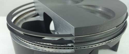
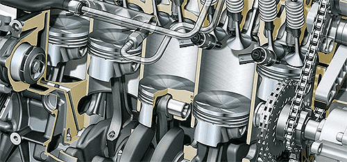
During the development of an IC engine, a working prototype may be created to test its overall durability and performance. This prototype can be used to obtain baseline operational data for the engine, including data for the ringpack (cut-away above). Some of the main issues that a ringpack engineer is concerned with are:
-
Blowby: pressure loss due to gas escaping through the ringpack
-
Blowback: the reverse of blowby; blowback gasses may be saturated with oil, causing decreased emissions performance of the engine
-
Wear and failure: excessive movements of the ring or starvation of lubrication in the engine may result in increased wear, or even failure and disintegration of rings
In this post I will focus on the issue of blowby. Blowby is easily tested on a prototype engine by measuring the amount of gas escaping from the sump of the engine. The experimental numbers from the prototype engine are then used as a baseline and as reference for tuning the simulation model.
The Simulation Model
The engine model I used is a purely hypothetical diesel engine and has a displacement of 1.5L per cylinder. A simple model may be thrown together in a few minutes using the CASE graphical user interface (GUI).
Tuning the Model
Once the engineer has some baseline blowby numbers, the engine model can be tuned to match the experimental blowby numbers. CASE uses simple linear flow models for gas-flow between different parts of the ringpack and, therefore, makes use of two flow coefficients:
-
discharge coefficients for complex discharge geometries
-
leakage coefficients for gas escaping between the micro-scale channels between two contacting rigid surfaces
Let’s say that the engineer ran the engine at the following load points having the resulting blowby:
| Engine Load (Bar) |
Engine Speed | Blowby (L/min) |
|---|---|---|
| 27 | 550 | 4.6 |
| 36 | 1800 | 5.4 |
| 41 | 2800 | 10.0 |
| 53 | 4000 | 12.4 |
Running it on Rescale
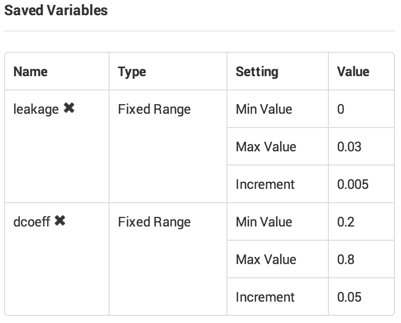
On Rescale, a 7×13 parameter sweep was set up for discharge coefficients (dcoeff) between 0.2 and 0.8 and leakage coefficients (leakage) between 0.0 an 0.03. The idea is to run the model at these parameter points and compare the output to the experimental numbers. The parameter point with the lowest difference between the experimental and the simulation data will be used to run subsequent design of experiment (DOE) simulations.
The input files were set up as a template, each one containing the corresponding template tags for each parameter.
DCOEFF ${dcoeff?string("0.00000")}
LEAKAGE ${leakage?string("0.00000")}
To run all 4 load points, the command to run on Rescale was entered as:
for i in {1..4}; do cd condition_$i; casering53.exe data.DAT; cd ..; done;
A post-processing script was used to extract the blowby values for each load point, compare the blowby values to the experimental values and calculate an RMS error. The smallest error occurred at point (dcoeff=0.70, leakage=0.01). The entire setup can be viewed by adding the shared job to your account.
Similar to running a parameter sweep, the engineer may use an optimizer to find the best match for these coefficients. Rather than optimizing over the entire domain, for pure demonstration purposes, I have set up and run an optimization job that refines the results of the previous parameter sweep searching in the domain (dcoeff=0.60-0.80, leakage=0.00-0.02). The setup of the optimization job can be viewed by adding the shared job to your account. The best result is conveniently highlighted with a green bar on the results page.
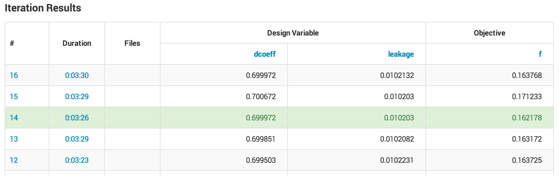
The results of these two jobs are shown below. The RMS error for the parameter sweep was 0.4060 L/min, while the refined RMS error was 0.4027 L/min.
| Blowby (L/min) | ||
|---|---|---|
| Experimental | Best Sweep Point | Refined Point |
| 4.60 | 4.97 | 5.04 |
| 5.40 | 5.88 | 5.96 |
| 10.00 | 9.86 | 10.00 |
| 12.40 | 11.88 | 12.02 |
The entire domain can be plotted as a response surface using Rescale visualization tools:

Engineering Analysis
We now have a tuned model and can do some real engineering work. The following example cases are implemented using the same workflow setup tools available in Rescale.
Minimize Blowby by Changing Static Twist
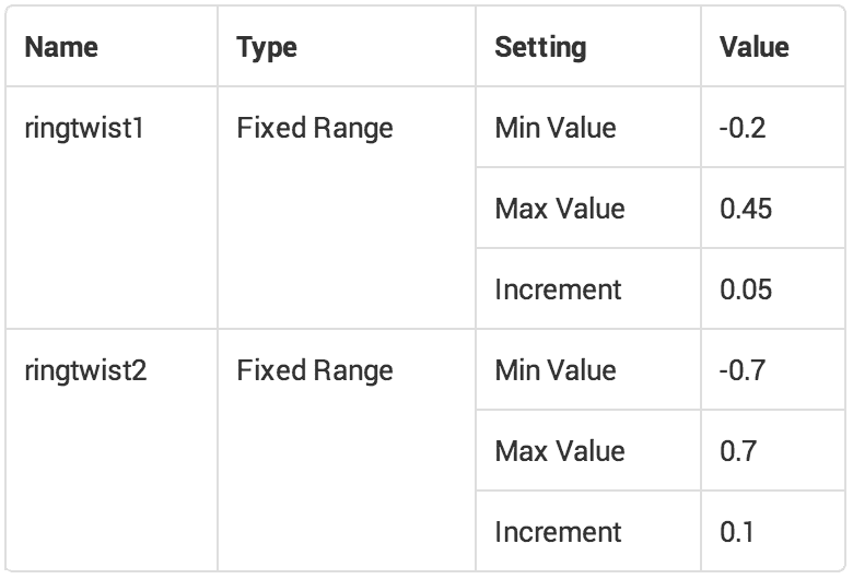
Let’s assume we want to optimize our ring design to minimize blowby. It is easy to change certain geometric properties of the ring. One of these properties is the ring static twist. This property describes the rotation of the ring cross-section relative to its nominal angle (0 degrees). We can run a quick parameter sweep on this geometric property using Rescale, similar to how we set up the tuning sweep. I set up a cross-product parameter sweep for the twist of the compression ring (ring 1) and the twist of the scraper ring (ring 2):
Let’s look at the results. To display the results, I have chosen the Area Chart option of the Rescale visualization tools. The blue colors denote low blowby (good!) and the red colors correspond to high blowbay (bad!). Interestingly, the chart shows that the twist of the first ring and the second ring do not independently affect the total blowby as there is no clear smooth trend.
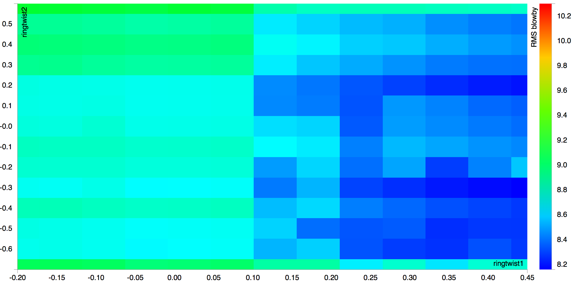
There are some interesting conclusions an engineer can draw from these results. The entire setup can be viewed by adding the shared job to your account.
And here’s a second study:
Minimize Blowby by Changing Groove Geometry
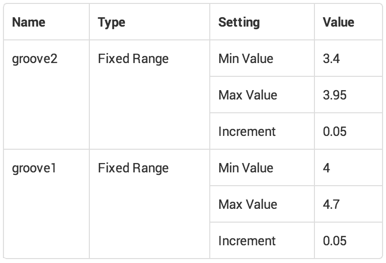
Let’s now look at the geometry of the grooves in which the rings reside. This time we changed the width of the groove of both the top and bottom grooves:
Let’s look at the results. Once again, to display the results I have chosen the Area Chart option of the Rescale visualization tools. Blue colors denote low blowby and the red colors correspond to high blowbay. This time, the chart shows that the geometry of the first and second groove independently affect the total blowby as there is a clear trend from the bottom left of the graph to the top middle.
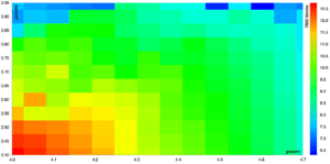
The entire setup can be viewed by adding the shared job to your account.
Summary
Even serial codes can be massively scaled out for the right applications. Rescale provides workflow tools to improve the process of scaling out simulation software. Not only can these codes be easily scaled out, embarrassingly parallel applications like parameter sweeps scale linearly, so there is no cost-performance loss. Rescale also provides visualization tools to summarize date in a single plot or chart, helping engineers process output information faster.
CASE is a cylinder-kit analysis suite developed by Mid-Michigan Research. For licensing or more information about the analysis software used, please contact sales@mmrllc.com or Harold Schock at harold.schock@mmrllc.com.
Please check out our paper entitled “Piston Ring Wear Analysis for Diesel Engines” later this year at ICEF2014.